ABOUT LMC
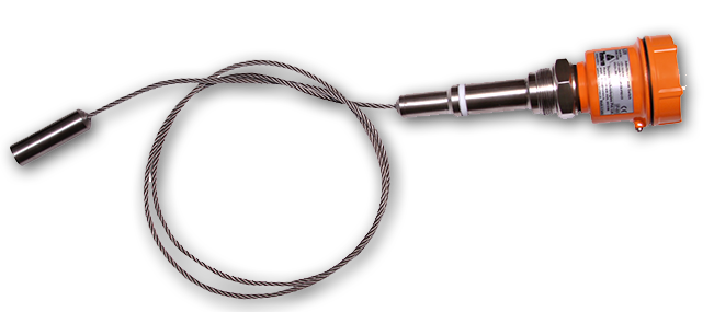
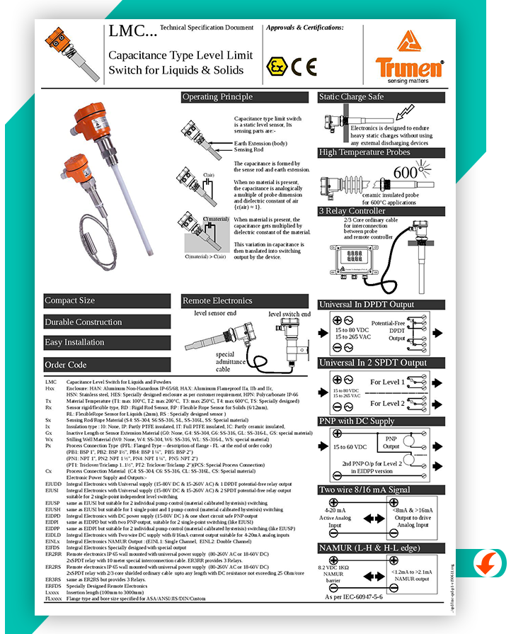
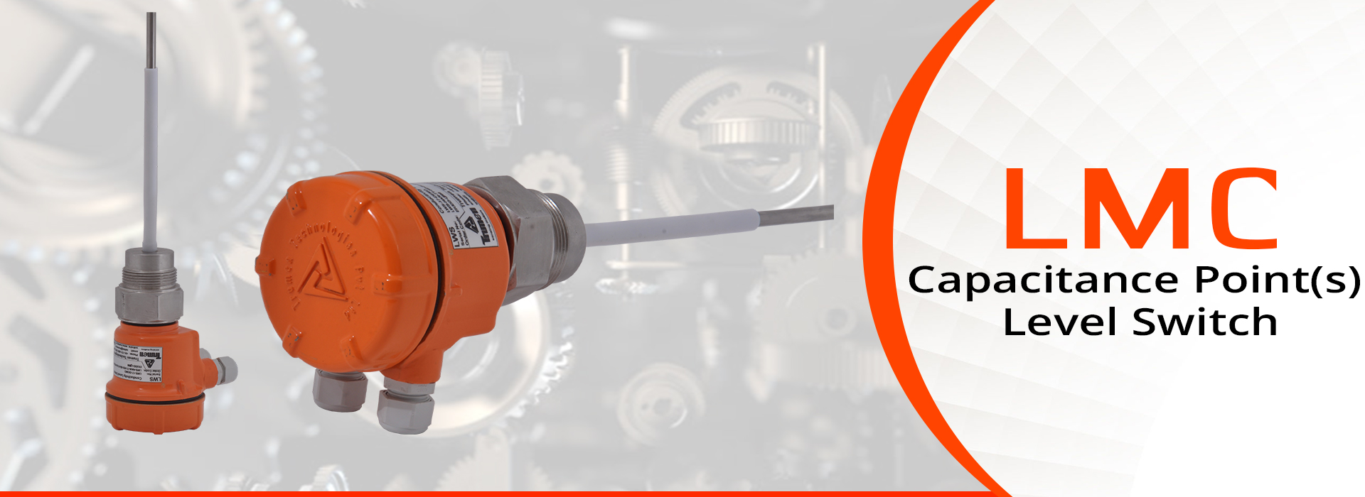
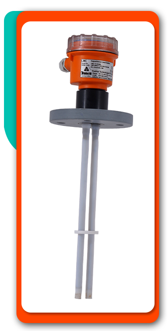
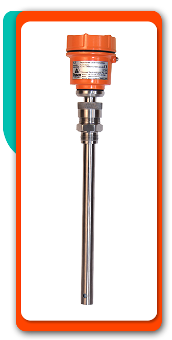
Trumen capacitance type point level switch model LMC suitable for conductive and nonconductive flow able liquids and free flowing bulk solids and powder.
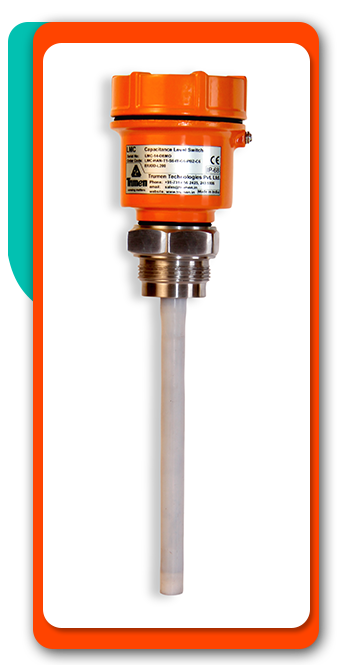
Trumen LMC available with Fully or partially PTFE or ceramic insulated rod probe or flexible rope probe depends on the process requirements.
ABOUT TRUMEN
Trumen came into existence in 2009 and initially started with manufacturing of Tuning Fork Level Switches in India for liquid and solid applications.
With time, the manufacturing range increased with addition of Capacitance Level Transmitter & Capacitance Level Switches, RF Admittance Level Switches, Rotating Paddle Level Switches, Conductivity Type Level Switches, Vibrating Rod Level Switches, Hydrostatic Level Transmitter, Radar.
FEATURES
- Compact in size.
- Easy calibration with or without material.
- Universal power supply on same terminal(15 to 80VDC & 15 to 260VAC).
- Customized process connection threaded / flanged / hygienic etc.
- Single sensor allows pump-control & multi-point switching.
- Inbuilt settable switching delay 5 sec.
- Various output option.
- Tropicalized sealed electronic module for easy maintenance.
- Remote Electronics version available on request.
APPLICATION
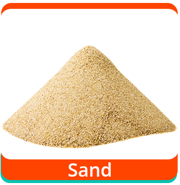
- Trumen capacitance level switch model LMC is used in different applications like Edible Oil, Diesel, Water, Acids, Solvents, Sand, glass aggregate, lime, ore (crushed) etc.
- Flush mount probe construction for small insertion to avoid heavy impact of lumps, rocks and bolder etc.
- Process temperature maximum 250°C with PTFE insulation and 600°C with ceramic insulation.
- Process Pressure up to 20 bar maximum.



OPERATING PRINCIPLE
Operation for LMC – UD Single Point Switching
Device operation and settings:
Trumen capacitance point level switch is very easy to operate-

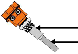
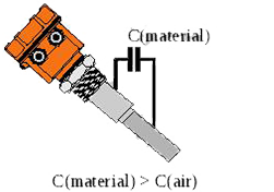
- LMC probe is make with two elements sense element, and ground element i.e. process connection either thread or flanged.
- Installed the LMC in to tank properly and make sure sensor ground i.e. process connection should be connected to the metalic
tank or hopper or silo. In case of non metallic tank we need to provide external metallic ground for better operation of LMC. - Open the cover of Trumen LMC and you can see there are 9 terminals.
Terminal 1, 2 & 3 are for auxiliary power supply. Terminal 4, 5, 6 & 7, 8, 9 for relay otput. - There are 6 DIP switches provided on connection panel Via DIP
Switch no.1 we can calibrate the instrument in air or in material
Switch no. 2 is to set dry delay.
Switch no. 3 is to set wet delay.
Switch no. 4 is to set fail safe.
Switch no. 5 is to set sensitivity 2pF or 8pF selectable For small probeor low dielectric material like diesel, edible oil, DM water etc keep the DIP switch no.5 is in OFF position for 2pF sensitivity, And for longer probe length with conductive material like Water, Conductive Solvent, Acid etc keep the DIP Switch No. 5 is in ON position for 8pF Sensitivity.
Switch no. 6 is range selection for low dielectric materials (500pF) like diesel or edible oil
or high dielectric materials like water or conductive liquids (1800pF). - Connect the power supply either 15 to 80VDC or 15 to 260VAC on terminal 1 & 2. Connect the earth on terminal 3 and switch on the power.
- Trumen LMC is ready to calibrate in air, make sure that material should below the sensor. You can see LED 1 of process bar blink continuously and alarm led is in off condition.
- Now we turned on the switch no.1 to calibrate LMC in air.
The process bar will animate for 5 sec After 5 sec all 6 leds are turned on.
Now the 6th led of process bar start blinking and turned off. - This means that the device is setting itself 1pF insensitive when led is blinking and 2pF insensitive when led is turned off per led to current level for 2pF sensitivity.
- Turned off the switch no.1 when 3rd led of process bar is blinking. Now The device setting itself 5pF insensitive to current level for 2pF sensitivity. The sensitivity selection is applicable for low dielectric or dry materials.
- Now we fill the material Liquid up to the probe level.
- You can see the process bar leds starts blinking and turned on one by one from 1 to 6 Once the 6th LED turn on, immediately alarm led also turned on means liquid touches the probe.
- Relay status also change from NC to NO.
- Now we empty the material, you can see the process bar led start blinking and turned off from 6 to 1 and alarm led also turned off means material goes below the probe level.
- Switch no.2 is to set dry delay means off delay. ON the DIP switch no.2 and empty the material. LMC will wait for 5 sec once the material goes below the sensor and after 5 sec it generate switching. During delay cycle sensor avoids turbulence .
- Switch no.3 is to set wet delay means on delay. ON the DIP switch no.3 and fill the material. LSV will wait for 5 sec once the material touches the sensor and after 5 sec it generate switching. During delay cycle sensor avoids false switching.
- Fail safe can be set via DIP switch no.4 when the probe is installed for high level, Keep the DIP switch no.4 is turned-off, fail safe high or maximum and when the probe is installed for low level keep the DIP switch no.4 is turned-on, failsafe low or minimum.
- You can easily replace the electronics as shown.
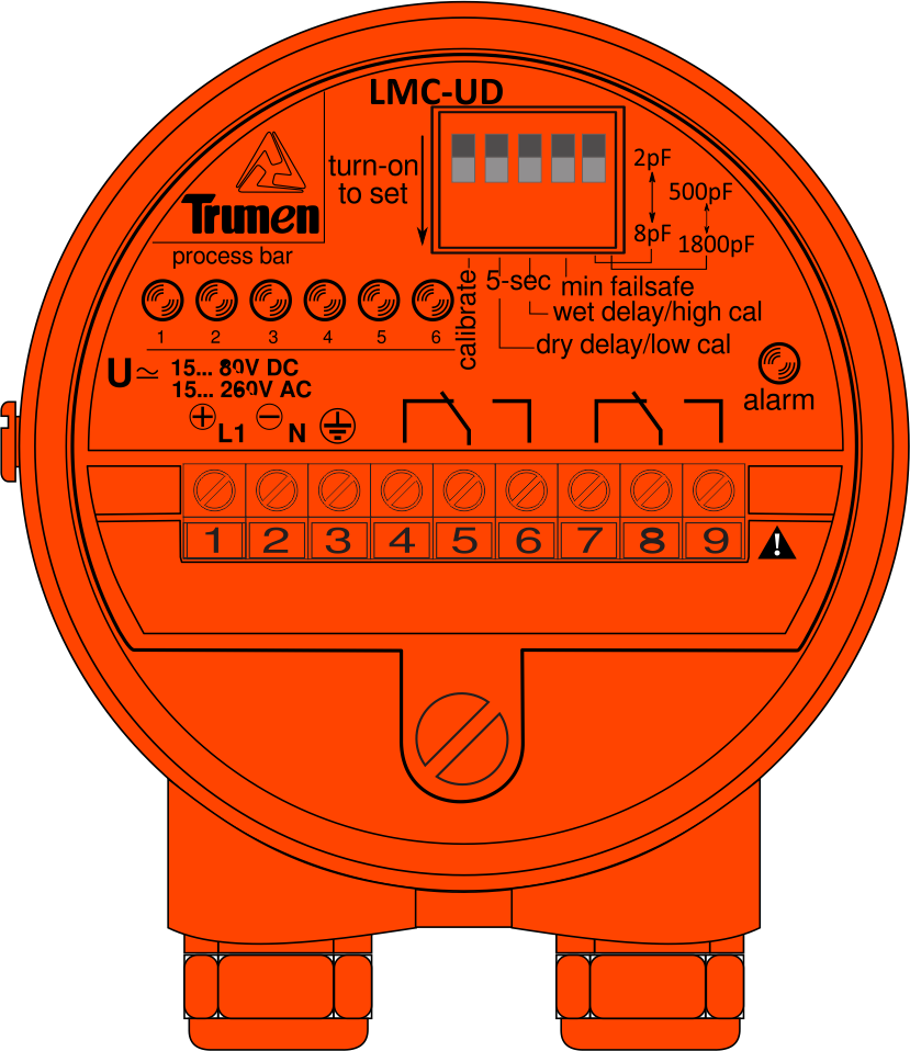
Connection Terminals
- + of DC or Live of AC Supply input
- – of DC or Neutral of AC Supply input
Supply:
15 to 80VDC or 15 to 260VAC 50/60Hz - Supply earth terminal for safety
- Normally connected terminal of contact 1
- Common terminal of contact 1
- Normally open terminal of contact 1
- Normally connected terminal of contact 2
- Common terminal of contact 2
- Normally open terminal of contact 2
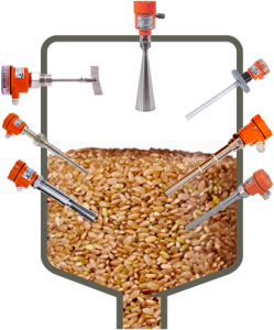
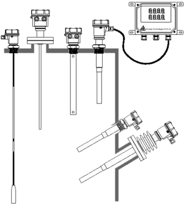
TYPICAL MOUNTING
PRODUCT VIDEO
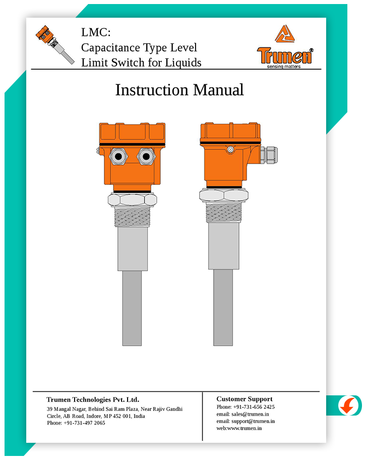
TECHNICAL DATA & INSTRUCTION MANUAL
TESTIMONIALS
WHAT OUR
HAPPY CLIENTS
SAYS ABOUT US
TRUMEN LMC USERS
UK

UAE

Turkey

Tanzania

Poland

Malaysia

Lithuania

Macedonia

Iran

Italy

Denmark

Chile

France

Japan

Argentina

Kuwait

Canada

Sri Lanka

Korea

Thailand

USA


